
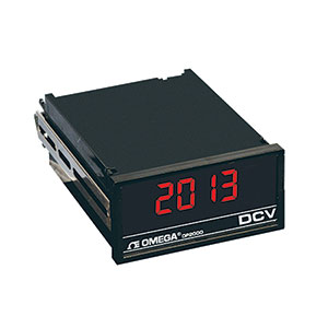
DC Voltmeter, Ammeter Indicator/ Controller, 1/8 DIN
imagem meramente ilustrativa
Descrição
Starting from Apr 1st 2018, DP2000/9000 Series have been discontinued. As a possible substitute, please check out the DPPT Panel Meter or DP20 Series for details.