| 

Digital Input Panel Meter - Count and Rate meter

DPF9300

Digital Input panel meter | DPF9300

Digital Input panel meter

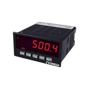
imagem meramente ilustrativa

2 anos de garantia CE
  • Count, Dual Count, Rate and Slave Display
  • 50 x 97 mm (2 x 3.8")
  • 6-Digit, 14 mm (0.56") LED
  • Variable Intensity Display
  • 10-Point Scaling for Non-Linear Inputs (DPF9300 Series)
  • NEMA 4X(IP65) Sealed Front Bezel
Instrumentação e Acessórios - Ver Produtos Relacionados

Descrição

The DPF9300 digital input panel meter offers many features and performance capabilities to suit a wide range of industrial applications. The DPF9300 offers both counting and rate in the same package. The optional plug-in output cards allow the opportunity to configure the meter for present applications, while providing easy upgrades for future needs. The meters employ a bright 14 mm (0.56") LED display. The intensity of the red LED display can be adjusted from dark room applications up to sunlight readable, making it ideal for viewing in bright light or dark room applications. The meters accept digital inputs from a variety of sources including switch contacts, outputs from CMOS or TTL circuits, magnetic pickups and all standard RLC sensors. The meter can accept directional, unidirectional or quadrature signals simultaneously. The maximum input signal varies up to 34 KHz depending on the count mode and function configurations programmed. Each input signal can be independently scaled to various process values. The rate meters provide a MAX and MIN reading memory with programmable capture time. The capture time is used to prevent detection of false max or min readings which may occur during start-up or unusual process events. The meters have four set point outputs, implemented on plug-in option cards. The plug-in cards provide dual FORM-C relays (5A), quad FORM-A (3A), or either quad sinking or quad sourcing open collector logic outputs. The setpoint alarms can be configured to suit a variety of control and alarm requirements. Communication and Bus capabilities are also available as option card through the bus. Additionally, the meters have a feature that allows a remote computer to directly control the outputs of the meter.

With an RS232 or RS485 card installed, it is possible to configure the meter using free software. The configuration data can be saved to a file for later recall. A linear DC output signal is available as a plug in option card. The card provides either 20 mA or 10V signals. The output can be scaled independent of the input range and can track any of the counter or rate displays.

Once the meters have been initially configured, the parameter list may be locked out from further modification in its entirety or only the set point values can be made accessible. The meters have been specifically designed for harsh industrial environments. With NEMA 4X (IP65) sealed bezel and extensive testing of noise effects to CE requirements, the meter provides a tough yet reliable application solution.

SPECIFICATIONS
Display: 6-digit, 14.2 mm (0.56") red LED, (-99999 to 999999)
POWER
AC Powered Units: 85 to 250 Vac, 50/60 Hz, 18 Va
Isolation: 2300 Vrms for 1 min. to all inputs and outputs (300V working)
DC Powered Units: 11 to 36 Vdc, 14 W (derated operating temperature to 40°C (104°F) if operating <15 Vdc and three plug in option cards are installed)
AC Power: 24 Vac, ±10%, 50/60 Hz, 15 Va
Isolation: 500 Vrms for 1 min. to all inputs and outputs (50V working)
Sensor Power: 12 Vdc, ±10%, 100 mA max short circuit protected
Keypad: 3 programmable function keys, 5 keys total
User Inputs: Three programmable user inputs
Max Continuous Input: 30 Vdc Isolation to Sensor Input Commons: Not isolated
Logic State: Jumper selectable for sink/source logic
INPUT STATE
Sinking Inputs: 5.1KΩ pull-up to +12V
Active: Vin<0.9 Vdc
Inactive: Vin>3.6 Vdc
Sourcing Inputs: 5.1KΩ pull-down
Active: Vin>3.6 Vdc
Inactive: Vin<0.9 Vdc
Response Time: 6 msec. typical; function dependent. Certain resets, stores and inhibits respond within 25 ìsec if an edge occurs with the associated counter or within 6 msec if no count edge occurs with the associated counter. These functions include CtrStL, CtrStE, HLrStL, HLrStE, INHlbt, StOrE, and PrNsSt. Once activated, all functions are latched for 50 msec min. to 100 msec max. After that period, another edge/level may be recognized
Memory: Nonvolatile E2PROM retains all programmable parameters and display values.
ENVIRONMENTAL CONDITIONS
Operating Temperature Range: 0 to 50°C (32 to 122°F) [0 to 45°C (32 to 113°F) with all three plug-in cards installed]
Storage Temperature Range: -40 to 60°C (-40 to 140°F) Operating and Storage Humidity: 0 to 85% max relative humidity non-condensing
Altitude: Up to 2000 meters
Connections: High compression cageclamp terminal block
Wire Strip Length: 7.5 mm (0.3")
Wire Gage: 30-14 AWG copper wire
Torque: 4.5 inch-lbs (0.51 N-m) max
Construction: This unit is rated for NEMA 4X/IP65 outdoor use. IP20 Touch safe. Installation Category II, Pollution Degree 2. One piece bezel/case. Flame resistant. Synthetic rubber keypad. Panel gasket and mounting clip included.
Weight: 10.1 oz (286 g)
COUNTER DISPLAYS Maximum Display: 8 digits: ± 99999999 (greater than 6 digits display alternates between high order and low order)
RATE DISPLAY Accuracy: ±0.01%
Minimum Frequency: 0.01 Hz
Maximum Frequency: 34 KHz (depending on set-up)
Maximum Display: 5 Digits: 99999 Adjustable Display (low) Update: 0.1 to 99.9 seconds
Over Range Display: "rOLOL"
INPUTS A or B: DIP switch selectable to accept pulses from a variety of sources including switch contacts, TTL outputs, magnetic pickups and all standard RLC sensors.
Logic: Input trigger levels VIL=1.5V max; VIH=3.75V min.
Current Sinking: Internal 7.8 KΩ pull-up to +12 Vdc, IMAX=1.9 mA.
Current Sourcing: Internal 3.9 KΩ pull-down, 7.3 mA max @ 28 Vdc, VMAX=30 Vdc.
Filter: Damping capacitor provided for switch contact bounce. Limits input frequency to 50 Hz and input pulse widths to 10 msec. minimum.
MAGNETIC PICKUP Sensitivity: 200 mV peak
Hysteresis: 100 mV
Input Impedance: 3.9 KΩ @ 60 Hz
Maximum Input Voltage: ±40V peak, 30 Vrms
DUAL COUNT MODES When any dual count mode is used, then User Inputs 1 and/or 2 will accept the second signal of each signal pair. The user inputs do not have the Logic/Mag, High/Low Freq, and Sink/Source input setup switches. The user inputs are inherently a logic input with no low frequency filtering. Any mechanical contacts used for these inputs in a dual count mode must be debounced externally. The user input may only be selected for sink/source by the User Jumper placement.
We noticed you are from the US. Visit your local site for regional offers and live support.