Finned Tubular Air Heating Elements
imagem meramente ilustrativa
Descrição
The FTS series has been discontinued. Please contact our Temperature Engineering department for a viable replacement.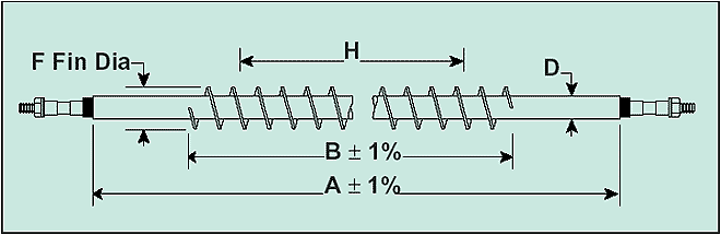
| Model No. | Watts | Volts | Dimensions cm (in) | |||
| A | B | F | H | |||
| 0.80 cm (0.315") Sheath Diameter (D) Approximately 60 W/sq. in. | ||||||
| FTS-015315/120V | 500 | 120 | 38 (15) | 26.7 (101/2) | 2.14 (.844) | 20.2 (81/4) |
| FTS-024315/120V | 1025 | 120 | 61 (24) | 49.5 (191/2) | 2.14 (.844) | 42.3 (171/4) |
| FTS-036315/120V | 1750 | 120 | 91 (36) | 80 (311/2) | 2.14 (.844) | 71.1 (291/4) |
| FTS-048315/240V | 2450 | 240 | 122 (48) | 110 (431/2) | 2.14 (.844) | 101.1 (411/4) |
| FTS-063315/240V | 3500 | 240 | 160 (63) | 149 (581/2) | 2.14 (.844) | 137.8 (561/4) |
| 1.2 cm (0.475) Sheath Diameter (D) Approximately 9.3 W/cm2 (60 W/in2) | ||||||
| FTS-015475/120V | 725 | 120 | 38 (15) | 26.7 (101/2) | 2.90 (1.14) | 22 (8 5/8) |
| FTS-024475/120V | 1450 | 120 | 61 (24) | 49.5 (191/2) | 2.90 (1.14) | 45 (17 5/8) |
| FTS-036475/240V | 2450 | 240 | 91 (36) | 80 (311/2) | 2.90 (1.14) | 75 (29 5/8) |
| FTS-048475/240V | 3450 | 240 | 122 (48) | 110 (431/2) | 2.90 (1.14) | 106 (41 5/8) |
| FTS-063475/240V | 5000 | 240 | 160 (63) | 149 (581/2) | 2.90 (1.14) | 144 (56 5/8) |
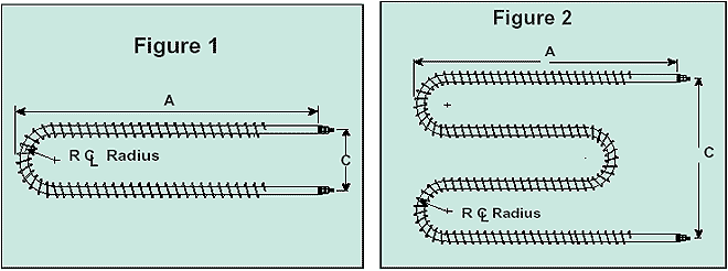
| Element Dia. cm (in) |
Factory Min C |
Bending Min R |
Customer Min. C |
Bending Min. R |
| Figure 1* | ||||
| .800 (.315) | 5.87 (2 5/16) | 2.78 (1 3/32) | 5.87 (2 5/16) | 2.94 (1 5/32) |
| 1.20 (.475) | 8.57 (3 3/8) | 4.29 (1 11/16) | 8.57 (3 3/8) | 4.29 (1 11/16) |
| Figure 2** | ||||
| .800 (.315) | 17.6 (6 15/16) | 2.62 (1 1/32) | 24.8 (9 3/4) | 2.62 (1 1/32) |
| 1.20 (.475) | 25.7 (10 1/8) | 4.29 (1 11/16) | 34.4 (13 9/16) | 4.29 (1 11/16) |
| * The overall length of A will be slightly less than one-half the original sheath length, depending on bending radius. ** The overall length of A will be approximately 3.8 cm (11/2") longer than one-fourth of the original sheath length depending on the bending radius R. Note: the start of any bends should be no closer than 8.7 cm (37/16") for 1.2 cm (0.475") dia. or 9.2 cm (35/8") for 0.8 cm (0.315") elements, from the end of the sheath to prevent the heating element/cold pin junction from being located in the bend. |